The Grenade
Project RF-section
The "Grenade" is a 10 watt AM transmitter for the 40 meter band (6955 kHz).
It was designed, built and sold by "Radio Animal" of WKND.
The "Grenade" is a 10 watt AM transmitter for the 40 meter band (6955 kHz).
It was designed, built and sold by "Radio Animal" of WKND.
The Grenade originally came built with one x-tal (6955/6950) and a dipole antenna at just under 100 dollars U.S. It is a great little radio, roughly the size of a brick, and weigh in at well under half a kilo. With a dipole cut to frequency you can cover the USA from the Rockies to the Atlantic in the evening under decent conditions. Output power roughly 15 watts when running from a 12 volt battery (That is constant carrier, it peaks in the 50 watt range) and will do close to 20 watts when powered from a regulated power supply. The limiter/compressor is really what makes the Grenade great. Makes it possible for someone with no knowledge of radio production to plug in a Walkman type tape deck and go on the air. The rig is cased is in a black steel box, with a finned aluminium heat sink covering the top. The transmitter can run continuously for 3 straight hours in hot temperatures (85+ degrees Fahrenheit) and the rig barely gets warm to the touch. Unlike ham transmitters, this one can run several hours per day with no problems and it is made so that it can handle running into mismatched or even no antenna.
The Grenade
Project LF-section
The limiter/compressor is really what makes the Grenade great.
The limiter/compressor is really what makes the Grenade great.
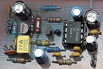
The
limiter/compressor in the Grenade Project LF-section.
The Grenade has an automatic level control to keep the audio level from being too loud or too soft. The circuit tries to compensate for differences in input levels, but some sources might still be too loud or too soft. If using a portable, like a boombox or personal stereo, adjust it for an average listening volume through the speaker, then connect it to the transmitter.
A resistive optocoupler, comprising an LED coupled to a photoresistor, has some unique advantages when used as a control element in analogue audio circuits. The devices consist of a high performance LED shining on a photocell inside a light-tight case. It's a light source and a photoresistor pointed at each other and sealed in an opaque package. It's pretty easy to make a limiter out of one: put a resistor in series with the photoresistor and drive your signal across the pair. Take the output across the photoresistor. Drive the light source (usually an LED) such that when the output level is too high, the light goes on and when it's too low, the light is shut off. When the light goes on, the photoresistor's and the resistor divider's loss increases value drops => the gain of the photoresistor's value increases and circuits drops. When the light goes off, the voltage loss of the divider decreases, raising the gain. That's all there is to it...
The only subtlety is how quickly the light turns on and off (or becomes brighter or darker) as this and the decay time of the photoresistor itself determines the attack and decay time of the limiter. The photoresistor is a typical Radio Shack thing the size of a dime, which has the LED touching the lens and pointing directly into it, with the whole mess sealed in a mass of black heat-shrink tubing pieces to block outside light. The photocell has a dark resistance of about 10 Megs and a LED-full-on resistance of a few hundred ohms.
Simple Modulators for solid-state Transmitters: Simple AM modulator work by varying the amount of power supplied to the transistor, which is serving as the RF output amplifier. By imposing an audio waveform on the power supply, amplitude modulation is achieved. A transformer less circuit is physically smaller and lighter than designs that use a modulation transformer. Transformer-based modulation methods have a more "warm" sound quality, while transformerless schemes have a "crisp" sound.
Audio level control device (compressor).
by G3YXM
Starting with an audio compressor. There have been umpteen designs for compressors published over the years but many of them are difficult to set up or cause distortion and others use expensive chips.
This one updates an old principal used years ago: a light bulb driven by audio illuminates an LDR in the feedback loop. The brighter the light tends to glow, the lower the resistance of the LDR becomes and the more negative feedback gets applied, reducing the gain. The LDR is purely resistive so the amplifier maintains good linearity.
The problem with a light bulb is its' thermal inertia, the attack time of the AGC circuit is too slow and you get distortion on peaks. What we needed was a fast light bulb.... We now have one, the light emitting diode!
The circuit is shown above and should cost about $15 if you have to buy all the bits new.
The NORP12 L.D.R has a dark resistance of around 1MegOhm but will come down to a few hundred Ohms in bright light. It's peak sensitivity is to yellowish light at a wavelength of around 580nM. The best match is, of course, a yellow LED. Toshiba have some nice bright ones with a peak output at 590nM which is close enough!
The crux of the thing is to mount the LDR and LED in close optical contact whilst being careful to exclude all stray light from the assembly. You can mounted them in a piece of black plastic tubing and sealed it with silicone rubber and black end-caps.
The op-amps are two halves of a TL072 and have enough gain to bring a mike insert up to a good loud line level. Performance has been measured as below.
Performance with gain set to Max.
Input level Output level theshold of compression 20uV RMS 1.9V RMS maximum input level 3mV RMS 2.6V RMS
40dB input range is compressed to 3dB output change.
Distortion is less than 0.2% within normal operating range.
Frequency response is 30Hz to 8kHz within 3dB at max gain.
The current drawn at 12V is only about 4mA.
Specialised components
- Op amp Chip TL072
- Light dependant resistor NORP12
- Toshiba yellow ultra-high-bright LED
The resistors are nothing special, 0.4W metal film are OK; the diodes are small signal diodes such as 1N4148 and the capacitors are at least 12V working.
Do not attempt to operate the circuit below 12V as there won't be enough drive to the LED and clipping will result. Using germanium diodes instead of silicon ones would give a little more headroom (and slightly reduce the output level ).
Larry Sparks NØBHU is building a low power AM transmitter for 75 meters. It's not too often we see a transmitter with a big audio chip and a modulation transformer. Here is Larry NØBHU's 75 meter AM transmitter. The heat sink on the right rear is for the modulator and the final PA is on the left front. He is getting about 9 watts of carrier power output .!
Why it is important to use a limiter?
Audio signals as music or speech have big dynamic ranges. There are silent and loud sections. These audio signals aren't too good for a transmitter, which requires audio signal with constant level on the input. Limiter is a device, which weakens loud signals and intensifies silent signals. On its output there is signal with constant level.
Technical specifications
Supply voltage: 10-14 V stab.
Supply currents: 20 mA
Audio input: impedance 20 kOhm, optional preemphasis
Output voltage: 0,4 V rms
Dynamic range: >50 dB
Output voltage vs. input voltage
Schematic diagram

Parts list
Resistors:
R1 - 68 k
R2 - 22 k
R3 - 180 k
R4 - 10 M
R5 - 10 k
R6 - 47 R
R7 - 240 k
R8 - 1,5 k
R9 - 820 R
Capacitors:
C1 - 100 p (ceramic)
C2 - 1 n (plastic)
C3, C6, C12 - 100 n (ceramic)
C4, C11, C13 - 100 u (electrolytic)
C5 - 0,33 u (tantalum)
C7, C8 - 10 u (electrolytic)
C9 - 220 n (plastic)
C10 - 47 n (ceramic)
C14 - 470 n (plastic)
Misc.:
T1 - BF245C
T2 - BC556B, BC307
IC1 - LM386
PCB
layout
No comments:
Post a Comment