Friday, July 11, 2014

LT1910 AM transmitter
This circuit uses an LT1190, LT1007, and an LT1194 to form a AM radio transmitter. The carrier is generated by A1, set up as a quartz stabilized oscillator. A1's output feeds A2, functioning as a modulated RF power output stage. A2's input signal range is restricted by the bias applied to offset pins 1 and 8. A3, a microphone amplifier, supplies bias to these pins, resulting in an amplitude modulated RF carrier at A2's output. The DC term summed with the microphone biases A3's output to the appropriate level for good quality modulation characteristics. Calibration of this circuit involves trimming the 50 ohm potentiometer in the oscillator for a stable 1Vp-p 1MHz A1 output. The construction and operation of this apparatus may require Federal Communications Commission review and/or licensing.
Sunday, July 6, 2014
Protect your MOSFET final stage
by G3YCC
This idea was described in Sprat 52 in 1982 and basically shows how, by the addition of two cheap components, a resistor and zener diode, mosfet PA's can be protected from destruction by over driving. This is described in the article by Alan G3UZU who mentions seeing this recommended in Radio Spares data sheet 5342 on power mosfets. The resistor limits the dissipation in the zener diode in series with it from gate to earth and can be 10 ohms, 1/4 watt. The zener voltage is found from data sheets. For example the commonly used VN46AF needs a zener of less than the maximum drive volts of 15, say 13v, 400mW. The ubiquitous VN10KM would need a zener of 4.7v, 400mw. For other devices, look up the data in many books and catalogues and note the maximum gate voltage quoted and choose an appropriate zener. This simple modification will be found very useful in homebrew transmitters.
Steve Quest's Transmitter
by S.Quest
In various newsgroups Steve Quest has described an AM transmitter for mediumwave and shortwave that has produced great results and is quite inexpensive. Here is the verbal description he offered:
However, for now, just picture a standard Pierce oscillator, crystal controlled on your frequency of choice, with the output connected to a standard class C amplifier stage. The only modification to the standard class C amp stage is the insertion (series, so cut the trace and insert) of a modulation transformer between the power supply line and the isolation inductor on the collector. What works great is the $1.95 at my local audio shop, SPECO line matching transformer. Connect the transformer backwards! In other words, the input side goes to the class C amp, and the output side, normally the side connected to the speaker becomes input. Transformers work both ways you know.
Use the 500 ohm and common taps on the class C amp side, and the 8 ohm and common tap on the input side.
Now hook up a power audio amplifier to the (now) input of the transformer, and a mic or other audio source to the line input of the power audio amp. Adjusting the volume on the audio power amp will increase and decrease your MODULATION! Use a scope to set your modulation, just lay the probe near the antenna to see the AM waveform. Adjust to about 80% modulation, don't overmodulate, it sounds like crap AND is quite inefficient.
*IMPORTANT* Use a chebichev filter between the output of the class C and your antenna! If you don't your harmonics will be over a watt for sure!
This configuration, when powered by 12 volts will generally give you an input power of about 5 watts. That's based upon the class C amp giving you a times 10 gain, and the input power from the Pierce oscillator of half a watt. Sloppy design of the Pierce, and poor tuning on the class C will cause the power to go DOWN. However, if you're good, you can get 10 watts or more by tweaking the Pierce up to a 1 watt output into the x10 class C stage.
About a 4 to 5 watt input signal to a 150 foot random-wire antenna on the 41 meter band during the average sunny winter day resulted in a clear signal copied at greater than 200 miles and a weak signal copied at 1000 miles. This range example is reproduceable by several successful tests.
And here is the schematic:
Parts List:
R1 = 47k 1/4w
C1 = .001uF
C2 = 470pF
C3 = 470pF
C4 = 100pF
C5 = .01uF
C6 = 470pF
C7 = 820pF
Y1 = 7.3728 Mhz series type (off the shelf, CPU application)
Q1 = ECG or NTE282 or similar
Q2 = ECG or NTE235 or similar
T1 = Speco type T7010 70 volt line matching transformer
L1 = 28turns around 1/4" ferrite overwrapped with 9turn secondary
L2 = 28turns around 1/4" ferrite
L3 = 1.5uH choke
To make L1, tightly wrap 28 turns, then wrap 9 turns over that tomake the secondary. Space the windings out to evenly cover thefull length of the 28 turns. Use light gauge enamel wire for all.
To connect the modulation transformer, wire backwards using the normal secondary as the primary. Connect the red wire of theinput side to Vcc and the black wire to the class C amp choke. Connect the output side white wire to the amplifier speaker jack positive, and the black wire to the speaker jack negative. Use the amplifier volume control to adjust modulation level.
A few more details of this circuit:
... since the rig operates in the 41 meter band, I just used generic CB radio transistors. The Pierce oscillator uses a generic CB radio driver transistor, and the final is a CB radio final. Thesetransistors are cheap, readily available, and probably will never beoutlawed (like I suspect VHF RF components will eventually be). Since CB radio is 27 Mhz, running them at 41 meters (7 Mhz) is very easy on them.
Any type NPN, TO-220 package CB radio driver and final will workfor this application. There are probably _better_ transistors out there,but these are cheap, available at the local radio shop, and already instock for those of us who fix a few CB radios from time to time.And here's some additional detail:
I get my forms from a distributor, and my inductors as well. However, I know there are ferrites that are "close enough" in the Radio Shack assortments. You should be able to find one fairly close.
The question this time is could one substitute say 5/16" core for L1 & L2 and adjust the windings to come out with the same results. If the answer is yes, then could you recommend a good starting point to make the alterations?
Sure, use a 5/16" core, and the same number of turns. Remember, I didn't specify the wire gauge, and I should have said "about 1/4" ferrite rod" instead of being exact. Use a heavy enough enameled wire that you don't vaporize it with current flow, I used the middle gauge out of the Radio Shack 3 pack for my windings. This fact should probably be added at the website. :) You may have to adjust secondary turns between the oscillator/driver and the final to tune for maximum power. Don't glue the windings and leave plenty of extra (not looped but curved up) so you can do that. Once you find the right amount, glue them down. I use wax usually, but have also used shellac, varnish, silicone, you name it.
On the inductor in the final, an extra few turns will not hurt, but don't take away! Same goes for the primary on the osc/driver. However if you add turns, you'll have to adjust the secondary turns and capacitors. One thing to remember with HF verses VHF, the windings are NOT as critical. 3 turns in an air wound VHF oscillator tank coil will get you, let's say 88 Mhz, and one more turn and you're down to 64 Mhz, and another and you are in the 40's. It isn't like that with HF, it's not so touchy.
A small two stage transistor AM transmitter
This is two-stage transistor AM transmitter for the shortwave band, which gives about 1 watt in output. You can use a 2N2219 or a 2N3553 in the final stage. The output with a 2N3553 is aprox. 1.8 watt @ 12 Volt. The transmitter seems to give more output when you use 7 turns instead of 4 turns in the secondary section of T1 (the coil between oscillator and final stage). It will work fine between 6 and 8 MHz. Try with different (power) transformers to modulate the transmitter in Amplitude Modulation. You have to do experiments to find a suitable modulation transformer to produce a good Amplitude Modulation.
Also test with different transistors in the final stage, but be careful to not blow up the rig.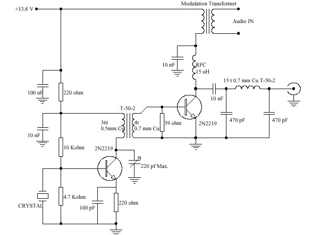
Simple Class E Transmitter
Class E amplifiers are very efficient amps and are generally built with MOSFET transistors. The principle is to drive the MOSFET's gate input with square waves to quickly put the device into it's low ohmic region and to do this when the voltage across the drain of the MOSFET is at or near zero volts. This greatly reduces the heat dissipated by the MOSFET and increases efficiency. A choke value for the drain is chosen so that it resonates at the operating frequency, in combination with the parasitic capacitance of the drain and the output filter. The "fly wheel" effect of the resonant tank causes the drain voltage to drop to zero before the MOSFET is switched back on. Efficiencies of 70% or more can be achieved this way.
The circuit show below is a simple Class E transmitter and is shown built for 40 meters. It uses a 74HC02 NOR gate as a crystal oscillator. The other three gates in the package are used to gate the clock signal to the output MOSFET. The crystal oscillator can also be used with a direct conversion receiver. An Rx offset curcuit is shown to shift the oscillator frequency when receiving.
A 2N7000 is used for the final power amp. Although only one is shown, three '7000's are used in parallel to reduce the "on" resistance, which inproves efficiency. 70-75% efficiency can be achived. The amplifier delivers about 2 watts output with a 9 volt supply and about 4 watts with a 12 volt supply. The plastic TO-92 2N7000's bearly get warm to the touch.
For best results the spacing on the output filter inductors with need to be "tweaked". Monitor the drain current and output power and calculate efficiency. Adjust the spacing of the windings on the output filter inductors until you get the best efficiency. L2 will have the greatist effect. L5 and C15 are used to suppress VHF spurs, which aren't effectively attenuated by the HF low pass filter.
If the square wave drive to the fet is simply gated on and off, the keying waveform is very steep and causes key clicks. Therefore, the supply voltage to the PA needs to be ramped up and down in order to provide for a least some wave shaping. Q1 is a PNP power transistor which is turned on and off by Q2. C19 slows the turn on and turn off time down and causes the voltage on the collector to rise and fall with about a 5 ms time constant. R5 and C14 form a delay to keep the drive active to the PA while the supply is ramping down.
Grenade Transmitter
The Parts List for the Shortwave Transmitter:
- R1 - 33K ohms, ¼ watt, carbon.
- R2 - 4.7K ohms
- R3, R6 - 100 ohms
- R4 - 22 ohms
- R5 - 100 ohms, 1 watt, or greater.
- C1 - 47 to 470 pF, or greater, silver mica or disc ceramic. Better yet, a trimmer capacitor, to slightly change frequency ±1 KHZ.
- C2 - 10 to 140 pF trimmer.
- C3 - 100 to 220 pF, silver mica or disc ceramic.
- C4 - .01 to .05 µF.
- C5 - 300 - 800 pF, or (? ? ?) variable capacitor. Use an Arco TC-4610 (260-900 pF) compression trimmer.
- C6 - .01 to .1 µF.
- C7 - 1000 µF or greater, electrolytic, 25 volts or greater.
- X1 - Fundamental mode crystal, 5 to 8 MHz.
- T1 - On an Amidon T50-2 toroid core, primary is 26 turns of #28 magnet wire closewound, secondary is 2 turns wound over the primary windings.
- T2 - On an Amidon T50-2 toroid core, bifilar wind 6 to 8 turns of #18 magnet wire. See note 1 for details.
- L1 - 2 mH or greater, .5 ohm or less resistance. Use the inductor from Radio Shack p/n 270-0030A HD Noise Filter. One could also use the 4 or 8 ohm secondary of a medium sized audio transformer, or the secondary side (6 to 24 volts) of an AC mains power transformer.
- L2 - .7 µH. Wind 7 turns of #16 magnet wire on a 5/8 inch diameter form, then remove form.
- L3 - 1.4 µH. Wind 11 turns of #16 magnet wire on a 5/8 inch diameter form, then remove form.
- Q1 - 2N2222
- Q2 - 2N2907
- Q3 - IRF510 or IRF511 (Radio Shack p/n 276-2072A)
... and this is another Audio section without compressor/limiter
A slight modification in the LF/RF section of the Grenade transmitter
How to winding and installing a Toroid Coil
The transmitter's low-pass filter uses a high-Q toroid inductor wound on a T37-2 form (T37 means the powdered-iron form is .37-inches in diameter). When winding the Toroid Coil, the numbers of turns are counted inside the form (not on the outside). That means, if the instructions call for a 12-turn coil, you must pass the wire through the centre of the core 12 times. When winding this coil, be sure to pull each turn up tight before starting the next. If the coil is wound loosely, its inductance increases - a condition that may reduce transmitter output power. Count turns on inside of form. Tin leads with solder before installing. Pull each turn tight before winding the next. Finally, before installing the Toroid Coil be sure to tin both leads with solder. The coil wire is coated with heat-strippable enamel insulation that breaks down at soldering-iron temperatures. If you touch the tip of an iron to the end of the wire for several seconds, the insulation should start to melt, allowing solder to adhere to the copper underneath. If your iron is not hot enough to start this process, carefully scrape the insulation off with a small hobby knife and tin. If necessary, refer back to these instructions at any time during assembly
The "Grenade" 10 watt AM transmitter for the 40 meter band
The Grenade Project RF-section
The "Grenade" is a 10 watt AM transmitter for the 40 meter band (6955 kHz).
It was designed, built and sold by "Radio Animal" of WKND.
The Grenade originally came built with one x-tal (6955/6950) and a dipole antenna at just under 100 dollars U.S. It is a great little radio, roughly the size of a brick, and weigh in at well under half a kilo. With a dipole cut to frequency you can cover the USA from the Rockies to the Atlantic in the evening under decent conditions. Output power roughly 15 watts when running from a 12 volt battery (That is constant carrier, it peaks in the 50 watt range) and will do close to 20 watts when powered from a regulated power supply. The limiter/compressor is really what makes the Grenade great. Makes it possible for someone with no knowledge of radio production to plug in a Walkman type tape deck and go on the air. The rig is cased is in a black steel box, with a finned aluminium heat sink covering the top. The transmitter can run continuously for 3 straight hours in hot temperatures (85+ degrees Fahrenheit) and the rig barely gets warm to the touch. Unlike ham transmitters, this one can run several hours per day with no problems and it is made so that it can handle running into mismatched or even no antenna.
Low-pass filters
"Station WRNY is equipped with the latest device known to the world of radio engineering, called a harmonic suppressor, the effect of which is the elimination of the signals of WRNY from every frequency except that to which it has been assigned by the Government, which means, in fan language, that the station may be tuned in on only one setting of the dial." Radio News magazine, August 1925
A low-pass filter attentuates the energy above a specified cut-off frequency. These filters are used to reduce the intensity of harmonics so that they don't interefere with other signals. Most of this filters on this page were designed for various ham radio gear operating in the bands from 1.8 to 14 MHz.
Unless otherwise noted these filters have 50 or 52 ohms input and output impedance. Capacitances are expressed in picofarads, inductances in microhenries. Most authors recommend using silver-mica capacitors.
for transmit frequencies
in the range of C1 C2 L1
1500-2000 kHz 1800 1800 30 turns #26 wire on T-50-2 toroid
3500-4500 kHz 680 680 21 turns #22 wire on T-50-2 toroid
5500-7300 kHz 470 470 14 turns #22 wire on T-50-2 toroid
5500-7300 kHz 820 820 2.2
approx.
cutoff freq. C1 C2 C3 L1, L2
1200 kHz .0039 uF .0056 uF .0039 uF 6.8
1800 kHz .0033 uF .0043 uF .0033 uF 5.6
2000 kHz 1592 pF 3184 pF 1592 pF 3.98
7300 kHz 470 pF 1000 pF 470 pF 42 turns
#26 wire
on T-50-2

cutoff frequency
(in MHz) 30 dB attenuation
point (in MHz) C1,/C4 C2,/C3 L1,/L3 L2
2.16 4.0 820 2200 4.44 5.61
4.12 7.3 470 1200 2.43 3.01
7.36 12.9 270 680 1.38 1.70
10.37 15.8 270 560 1.09 1.26
Based on an article by Ed Wetherhold published in UK Short Wave (Dec. 1983).
Friday, July 4, 2014
Simple AM Transmitter
There are not many AM transmitters that are easier to build than this one because the inductor is not tapped and has a single winding. There is no need to wind the inductor as it is a readily available RF choke (eg, Jaycar Cat LF-1536). To make the circuit as small as possible, the conventional tuning capacitor has been dispensed with and fixed 220pF capacitors used instead. To tune it to a particular frequency, reduce one or both of the 220pF capacitors to raise the frequency or add capacitance in parallel to lower the frequency. Q1 is biased with a 1MO resistor to give a high input impedance and this allows the use of a crystal ear piece as a low cost microphone.

Simple AM Transmitter Circuit Diagram
Thursday, July 3, 2014
AM Transmitter
There are two main approaches to generating AM:
1. Generate the AM signal at a low level (power/amplitude), and boost it to the required output power via linear RF amplification, or
2. Generate the AM at the final power level by directly modulating the gain/amplitude of the final (Class-C i.e. non-linear) RF power amplifier.
There are pros and cons of both approaches and which technique you choose will be influenced by the required power levels, frequency response, audio fidelity and the devices to hand. By way of illustration, here's a simple AM audio transmitter I cobbled together using an ancient 1 MHz TTL oscillator (which consumes the bulk of the operating current shown!) as the frequency determining element. (I've used the second approach to AM modulation in this circuit - also known as "plate modulation" from the old valve transmitter technique of modulating the anode [plate] voltage of the output amplifier).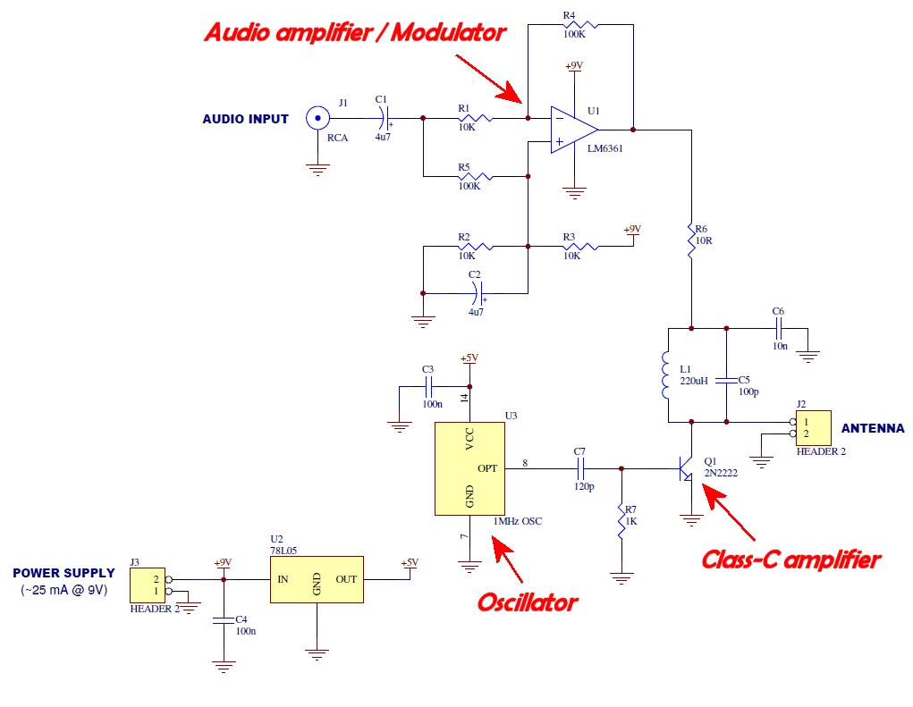
Sunday, June 29, 2014
A QRO HF DUMMY LOAD
100ohm power resistors for use in Wilkinson power splitters are often available at low cost. A pair of these resistors will make an excellent dummy load. I recently acquired a power film resistor which has four 50ohm resistors mounted on a large copper heatsink flange. As all of the resistors are connected to the mounting flange at one end, it was not possible to connect the resistors in a series/parallel combination to make 50ohm. The solution was to connect the four resistors in parallel to make a 12.5ohm load and use a 4:1 transmission line transformer to provide a 50ohm match. The transformer consists of two turns of RG58 on a Maplin N90AB ferrite core. This gives a perfect 1:1 SWR from 1.8 - 30MHz. The finished circuit is in Figure 6. Note that the DC voltage from the diode is only half the peak-input voltage because of the 2:1 voltage ratio of the transformer. I haven't been able to make much of an impression on this load during testing. Several minutes of SSB speech at 500W PEP will bring it from room temperature to lukewarm. I'm sure my transmitter would catch fire long before this load gets hot!
Saturday, June 28, 2014
5W 14MHz (20m) AM Transmitter
This is a simple audio transmitter for the 14MHz (20m) band. Its principle is seen from the diagram, so I will describe very briefly: The first stage is a simplified oscillator, the other three stages are amplifiers. The coils are wound on the 4mm diameter core with screw ferrite core to fine tune to the highest brightness of the light bulb. As a modulation choke, a secondary of small transformers (eg 220V/9V) is used. The tuning capacitor is also tuned for the highest brightness of the bulb. Then you can replace the bulb by a short. When you connect other antennas However, it is necessary to re-tune the output. Never operate without antenna!! Current consumption of the transmitter from the 12V supply during the normal operation of about 800mA. The coils have 30, 25 and 12 turns.
5W 14MHz (20m) AM Transmitter schematic
1W 7MHz (40m) AM Transmitter
This is a simple transmitter for amplitude modulation (AM) in the short wave band. It contains three transistors. The first stage as a quartz oscillator and can operate from about 4.5 MHz up to 12MHz. The second stage of the amplifier. For simplicity there is the resistor connected to collector and not coil. The third transistor is traditionally connected with the coil and forms the output stage. Using a DC-blocking capacitor it is connected to an antenna. For a simple start-up and high-quality sound it is modulated to the last stage. Sensitivity is therefore small, and the audio amplifier is required at the audio input. The AM modulation is built using the modulation inductor, which must have enough inductance. You can also use a secondary of small transformer. I used the secondary of the 220V/9V 1.6 VA transformer. Double choke in the oscillator has 2x 6 turns of wire 0.5 mm on the ferrite rod, 5mm diameter. Choke of output stage is without core and has 24 turns coil wire diameter of 0.5 mm wound on 10 mm diameter.
The circuit is powered by a well-filtered 12V voltage, current drawn is about 300mA. If you need to destroy the output power transistor, simplest way is to switch the transmitter on without the antenna connected :).
Thursday, June 26, 2014
Small Loop for 20 metres to 10 metres:
A loop for 20 metres or 17 meters is relatively compact and could easily be installed in small 'postage stamp' sized gardens. A loop antenna could be triangular, square (Quad) or circular, but a square loop (and indeed a circular loop) would need more supporting points than a delta (triangular) loop, so a Delta loop is likely to be the easier option.
The loop is really a single band antenna cut for one wavelength on the band of interest, however it can also work quite well as a cheap and easy to install multi-band H.F. aerial. A loop consisting of a 17 metre length of thin antenna wire, for example, will work well on 17 metres but may also give 15m, 12m and 10m with an ATU. My own loop is made from an 16 metre length of wire, tuned for the 17m band, but can work on higher bands. A 40 metre loop will be considerably larger, but it might still possible to accommodate in many fairly compact gardens. Performance will depend on height and orientation.
Feeding the loop at the top or bottom will give horizontal polarisation, while placing the feed point on the side will give vertical polarisation. The apex can be at the top or the bottom, but performance should be better with the apex at the bottom with the flat wire across the top - however for ease it may be more convenient to support a Delta Loop on a single pole, meaning that the apex would be at the top.
Ideally a loop should be fed with balanced line back to the shack, connected to a balanced line ATU or other ATU via a 4:1 balun. Alternatively use a 4:1 balun at the antenna end and run 50 ohm coax back to the ATU / txvr - though losses will be greater doing it by this method if the coaxial cable is quite long.
If one can install a separate antenna for the lower frequency bands of say 160m, 80m and 40m, then a Loop Antenna could be a good partner to allow operation on the higher bands of 20 metres to 10 meters or even 6 metres.
A loop should be really very easy to install using a single support pole and very cheap too! All that's needed is the supporting pole, some cheap wire, a 4:1 balun which can be 'home brewed' and some thin cord and insulators which should not be an eyesore either.

Diagram from the excellent article by W5SDC
http://w5sdc.net/delta_loop_for_hf.htm
Monday, June 23, 2014
Long Loopstick Antenna

Wound on a 3 foot length of PVC pipe, the long loopstick antenna was an experiment to try to improve AM radio reception without using a long wire or ground. It works fairly well and greatly improved reception of a weak station 130 miles away. A longer rod antenna will probably work better if space allows. The number of turns of wire needed for the loopstick can be worked out from the single layer, air core inductance formula:
Inductance = (radius^2 * turns^2) / ((9*radius)+(10*length))
where dimensions are in inches and inductance is in microhenrys. The inductance should be about 230 microhenrys to operate with a standard AM radio tuning capacitor (33-330 pF). The 3 foot PVC pipe is wound with approximately 500 evenly spaced turns of #24 copper wire which forms an inductor of about 170 microhenrys, but I ended up with a little more (213uH) because the winding spacing wasn't exactly even. A secondary coil of about 50 turns is wound along the length of the pipe on top of the primary and then connected to 4 turns of wire wound directly around the radio. The windings around the radio are orientated so that the radio's internal antenna rod passes through the external windings. A better method of coupling would be to wind a few turns directly around the internal rod antenna inside the radio itself, but you would have to open the radio to do that. In operation, the antenna should be horizontal to the ground and at right angles to the direction of the radio station of interest. Tune the radio to a weak station so you can hear a definite amount of noise, and then tune the antenna capacitor and rotate the antenna for the best response. The antenna should also be located away from lamp dimmers, computer monitors and other devices that cause electrical interference.
Magnetic loop antenna for 7-21 mhz
-
Magnetic Loop Diagram
-
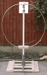
Magnetic Loop antenna

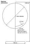
This antenna has several advantages, not least being only 1 metre diameter! This loop relies on being horizontally polarised and receives only the magnetic wave, thus as most noise in the domestic environment is vertically polarised and electrical wave, it delivers low noise to your transeiver/receiver, which makes for nice clean listening. In addition any signal arriving in the direction of the loop end on will be nulled out, this can be useful to get rid of an interfering signal by simply rotating the loop leaving the desired signal in the clear. It can be used indoors with ease and works well at ground level which is not the case for long wire/dipole antennas at shortwave wavelengths.
So what are its disadvantages? Well its tuning is critical, such that for a small change in frequency the antenna will need to be retuned at the loop end. This is even more important for transmitting where a high reflected wave (swr) due to not being tuned correctly will damage the output stage of your transmitter! In addition due to the very high "Q" of the loop, very high voltages can build up on the loop tuning capacitor even with low amounts of power from your transmitter. It is for this reason I recommend this loop is used with a transmitter of no more than 8 watts, any more and the ordinary broadcast tuning cap will arc over with spectacular results. Of course should you wish, a higher spec/bigger air spaced tuning cap would allow higher power output transmitters to be used. Also I consider the use of remote tuning using a fairly high geared motor and insulated coupling on the tuning cap essential. For shortwave listeners manual tuning would suffice.
In setting up the tuning of the loop, connect to a receiver and tune to 14 mhz. Now tune the loop which as it nears peak tuning will cause a whooshing sound. Stop the tuning you should now hear good strength signals in your receiver. For tuning for a transmitter, 1st use receive method then apply low power and fine tune loop tuning and tweak gamma match for lowest swr.
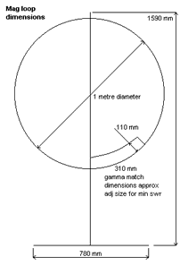
Magnetic loop dimension details
- Diameter of loop 1000mm
- Diameter of tube 15mm
- Width of base 780mm
- Diameter of support pipe 42mm
- Loop end spacing (for tuner) 50mm
- Height of support 1590mm
- Nylon board 210x240mm
- Nylon board 240x70mm
- Gamma match width 310mm
- Gamma/loop spacing 110mm
Construction Tips
- Use a bicycle wheel with no tyre on to help form the curves of the soft annealed copper tube
- Clean the tube with wire wool before any soldering
- Use a 100 watt soldering gun for the joints, but use a small blow torch first to get the copper at temperature to take a joint
- Force some timber with the corners planed off down the plastic plumbing pipe this will stiffen the pipe as the loop is quite weighty
- Use inverted shelf brackets to support the mounting pipe and make a wooden frame wide enough to hold up the loop
Saturday, June 21, 2014
Crystal AM Transmitter
Here is the circuit of a medium-power AM transmitter that delivers 100-150 mW of radio frequency (RF) power. At the heart of the circuit is a crystal oscillator. A 10MHz crystal is used to generate highly stable carrier frequency. Audio signal from the condenser mic is amplified by the amplifier built around transistors T1, T2 and T3. The amplified audio signal modulates the RF carrier generated by the crystal oscillator built around transistor T4. Here modulation is done via the power supply line. The amplitude-modulated (AM) signal is obtained at the collector of oscillator transistor T4.

Fig. 1: Circuit of crystal AM transmitter

Fig. 2: Oscillator coil 
Fig. 3: Modulation transformer
By using matching dipole antenna and co-axial cable, the range of signal transmission can be increased. For maximum range, use a sensitive radio with external wire antenna. The circuit works off a 9V-12V battery. For oscillator coil L1, wind 14 turns of 30SWG wire round an 8mm diameter radio oscillator coil former with a ferrite bead (see Fig. 2). For modulation transformer X1, you can use the audio output transformer of your old transistor radio set. Alternatively, you can make it from E/I section transformer lamination with inner winding having 40 turns of 26SWG wire and the outer winding having 200 turns of 30SWG as shown in Fig 3.
Low-Range AM Radio Transmitter
Here is a simple radio transmitter for transmission up to 25 metres. It is basically an AM modulator whose signal can be received on the normal AM radio. It can also be used as an AM radio tester.IC 555 (IC1) is used as a free running multivibrator whose frequency is set above 540 kHz. Here the circuit is designed for a frequency of around 600 kHz. The frequency of the multivibrator can be calculated as follows:
f=1.443(R1+2R2)C1

where resistors R1 and R2 are in ohms, capacitor C1 is in microfarads, and frequency f is in hertz. This frequency can be changed by simply replacing R2 with a variable resistor or C1 with gang capacitors. But it may increase the complexity of the circuit. A condenser microphone is used for speaking.
The IC 555 multivibrator is used as a voltage-to-frequency converter. The output of the condenser microphone is given to pin 5 of IC1, which converts the input voltage or voice signal into its appropriate frequency at output pin 3. This frequency produces an electromagnetic wave, which can be detected by a nearby radio receiver, and you can hear your own voice in that radio. Note that the receiver should be AM type. If there is no noise in receiver, tune it to 600 kHz.The circuit operates off a 9V regulated power supply or a 9V battery. For antenna, connect 2-3m long wire at pin 3.
CRYSTAL AM TRANSMITTER
The LM386 is a common integrated circuit that acts as an audio amplifier. These little things can actually make some pretty big sound. I've used them in a few projects, like my Arduino doorbell.
Pin diagram for the LM386 IC
The most important pins are 3 (your audio input), 6 (your voltage input), and 5 (your audio output). Pins 2 and 4 go to ground. A capacitor between 1 and 8 will increase your audio gain (a.k.a. louder volume). Pin 7 with a capacitor can be used to clean up the audio output. Checkout the datasheet for more information.
The transmitter circuit feeds the signal output of the LM386 into the crystal oscillator to modulate the RF signal. A few capacitors and a resistor are added to the LM386 as per its datasheet specs and to clean up the audio signal.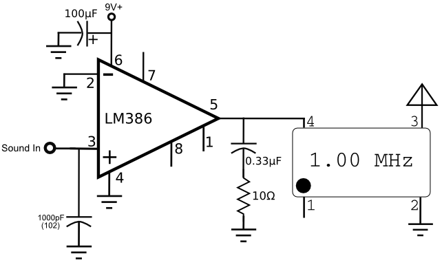
If you don't have all the parts for the lm386 portion of the circuit, don't worry. The only part here that really matters is the capacitor on pin 3, which helps increase the audio quality. The capacitor and resistor on pin 5 don't seem to make much of a difference, but I left them in because they are part of the standard lm386 build out from the data sheet. The capacitor on pin 6 where the voltage is input, smooths power fluctuations, but with a 9v battery input you don't need to worry about this too much.
After you power up your circuit and plug it into an audio source (like your phone), tune your radio to 1000 kHz and take a listen. If all went well you should hear music playing, and it should sound a lot better than the circuit in part 2. If the audio is distorted, try lowering the input volume on your phone / mp3 player. The distortion is overmodulation.
LONG RANGE SHORT WAVE TRANSMITTER
This transmitter circuit operates in shortwave HF band (6 MHz to15 MHz), and can be used for shortrange communication and for educational purposes.
The circuit consists of a mic amplifier, a variable frequency oscillator, and modulation amplifier stages. Transistor T1 (BF195) is used as a simple RF oscillator. Resistors R6 and R7 determine base bias, while resistor R9 is used for stability. Feedback is provided by 150pF capacitor C11 to sustain oscillations. The primary of shortwave oscillator coil and variable condenser VC1 (365pF, 1/2J gang) form the frequency determining network.
By varying the coil inductance or the capacitance of gang condenser, the frequency of oscillation can be changed. The carrier RF signal from the oscillator is inductively coupled through the secondary of transformer X1 to the next RF amplifier-cum-modulation stage built around transistor T2 that is operated in class ‘A’ mode. Audio signal from the audio amplifier built around IC BEL1895 is coupled to the emitter of transistor 2N2222 (T2) for RF modulation.
IC BEL1895 is a monolithic audio power amplifier designed for sensitive AM radio applications. It can deliver 1W power to 4 ohms at 9V power supply, with low distortion and noise characteristics. Sincen the amplifier’s voltage gain is of the order of 600, the signal from condenser mic can be directly connected to its input without any amplification.
The transmitter’s stability is governed by the quality of the tuned circuit components as well as the degree of regulation of the supply voltage. A 9V regulated power supply is required. RF output to the aerial contains harmonics, because transistor T2 doesn’t have tuned coil in its collector circuit. However, for short-range communication, this does not create any problem.The harmonic content of the output may be reduced by means of a high-Q L-C filter or resonant L-C traps tuned to each of the prominent harmonics. The power output of this transmitter is about 100 milliwatts.

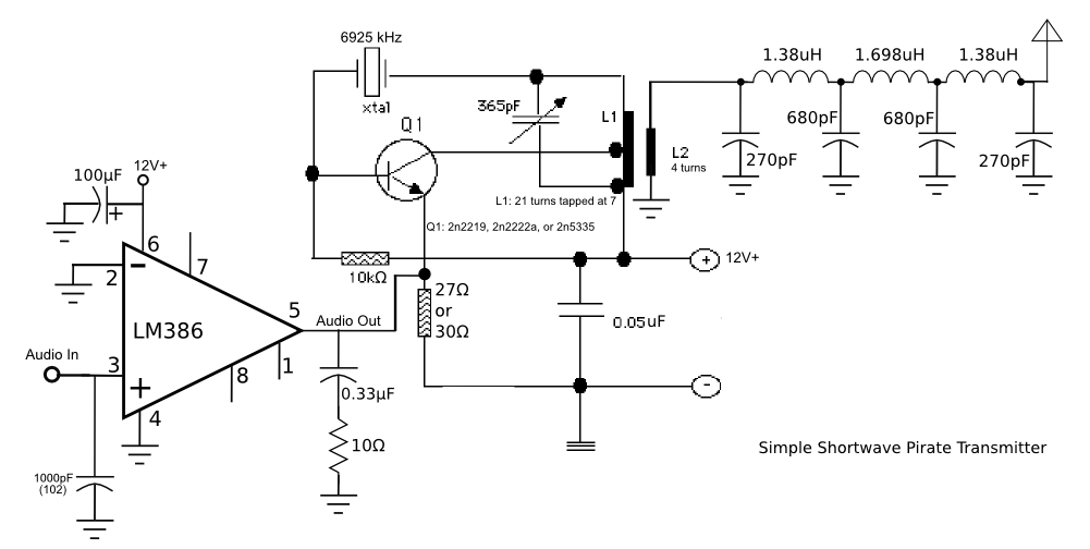
Shortwave Transmitter
The following schematic shows the three stages of our circuit. If you came across this article without reading my previous posts, and think this circuit looks difficult to build, it's not. Each stage is simple enough for novices to build, and the circuit is interesting enough for RF electronics experimenters to learn something. Hard to find parts can be found as usual by my recommendations here. Novices should try to build each stage of the circuit separately and ensure each works before putting it all together. The links provided for each stage cover in detail how each stage is built and how it works.
first stage is the audio modulator built from an LM386 IC with minimal parts. The modulated audio is fed into the second stage of the circuit which is the transmitter, configured for frequencies around 40 meters. The output of the second stage could be fed directly into an antenna or dummy load, but instead we will feed it into a third stage, a low pass filter, to filter out harmonics generated by the transmitter. The filter will ensure our signal only is present on the broadcast frequency, in this case 6925 kHz, a popular shortwave pirate frequency.
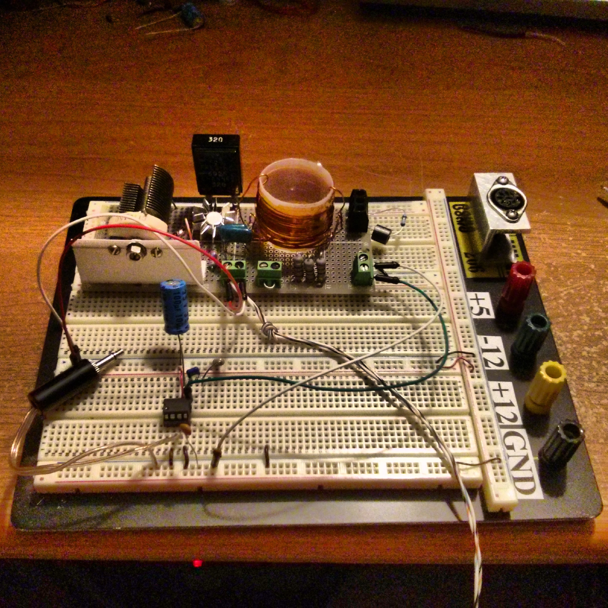
I recommend soldering this circuit up using perf board or using dead bug construction. Breadboard prototyping doesn't always work well for RF circuits, as they can add extra capacitance into the circuit. I was not able to get the low pass filter working properly until I soldered it up. The transmitter and audio modulator do seem to work on a breadboard, so your mileage may vary.
Here's a picture of the completed transmitter stage connected to the audio modulator on a breadboard. The transmitter is fed into a dummy load instead of the low pass filter, as I didn't want my signal to travel. The audio input is just a monaural headphones jack that can be plugged into a phone, mp3 player, or anything else with a headphones jack.


Friday, June 20, 2014
8.6-8.9 MHz AM Transmitter
On this post, I am going to show how to design an AM transmitter. AM transmitter is one of the simplest modulation system. Other simplest modulation system is CW (Continuous Wave). AM produced by adding information signal to carrier signal. This process is called wave superposition. Carrier signal is signal that carries information signal to another location. Carrier signal also called RF (Radio Frequency). RF spreads from lowest frequency of MF (Medium Frequency): 300KHz up to highest of Satellite Frequencies (around 15GHz).
Simple AM transmitter made of 2 stages. Preliminary stage consists of oscillator, and 2nd. stage consists of RF amplifier. You could add/design your own succeeding stages, thus improve output power and transmission distance.
When information signal is in form of directly added digital signal, this modulation is called ASK (Amplitude Shift Keying). This AM transmitter could also modulated by BPSK, QPSK and AFSK (Audio Frequency Shift Keying), but those signals of BPSK, QPSK, and AFSK should be formed first. On this research, I modulate carrier with analog signal only, so called "AM".
On this design, I have designed oscillator with Colpitts Oscillator system that has good frequency stability (fulfil certain criteria first). Class A RF amplifier stage built as voltage amplifier that tries to increase output AC voltage compared to input. Because transistor characteristic also increases current, this voltage amplifier also increases output power compared to input. Both oscillator and RF amplifier use common emitter configuration and NPN transistors. Output impedance of AF/RF Class A transistor amplifier with common emitter configuration is around 50,000 (50K) Ohms. Output impedance of any amplifiers could be downed using impedance transformer. Most of audio speaker have 8 Ohms impedance. In this case, needed 50,000 Ohms to 8 Ohms impedance transformer. Most of transmitter antenna have 50 Ohms impedance. In this case, needed impedance transformer that could change 50,000 Ohms into 50 Ohms. Output impedance of AF/RF PushPull Class B or Class AB transistor amplifier with common emitter configuration is around 100,000 (100K) Ohms. PushPull Class B transistor amplifier formed from 2 Class B transistor amplifiers put in parallel, output impedance forms series (50,000 + 50,000 Ohms). PushPull Class B or Class AB transistor amplifier works more efficient, because reduces existence of Collector Voltage, but works less linear compared to Class A. In Class A, there is Collector Voltage existence (consumes energy), but this Class A more linear compared to PushPull Class B or Class AB. Class AB PushPull amplifier is modification of Class B PushPull amplifier in order to reduce crossover distortion. So from side of linearity, Class A is best, Class AB PushPull is second, and Class B PushPull is third.
In order to design an oscillator or RF amplifier, you would need oscilloscope at least. There are various kinds of oscilloscope, eg. 5MHz oscilloscope could measure RF up to 5MHz accurately. 20MHz oscilloscope could measure RF up to 20MHz accurately. If oscilloscope used above specification, oscilloscope could still show current curve/graphic, but could not measure voltage or frequency accurately. Eg. if you like to design VHF FM transmitter with frequency around 90MHz, you would need at least 5MHz oscilloscope and frequency counter that could measure 90MHz. Oscilloscope needed especially to measure voltage amplification accurately.
RF amplifier voltage amplification (on this design): 0.5Vpp/2.3Vpp= 0.217 . Current-gain bandwidth product (fT) of 2SC2053 is not mentioned in 2SC2053 DataSheet. In DataSheet only mentioned that 2SC2053 is transistor for VHF RF Amplifier. That's why I didn't doubt to use this transistor. Transistor with VHF purpose could be used at HF and AF. Maximum frequency of VHF is 300MHz, so I assumed fT little beat higher than 300MHz. Assumed 2SC2053 fT=400MHz ---> ßrf=400/8.8=45.45 so power gain/amplification=0.217x45.45=9.86 .
This means if earlier stage produces z Watts, this RF amplifier would increase power to 9.86z Watts.RF amplifier principle is to amplify power from stage to stage. Succeeding stage should have more power compared to earlier. This principle could be used if you don't know fT of one transistor. Just estimate fT of that transistor, keep calculate, and after you've finished particular stage, just check its power. Its power should be more compared to earlier stage. If you are designing RF amplifier, you could check S (signal) meter at receiver that shows power strength of particular transmitter. If that stage fails to improve power, you should recalculate that amplifier. In my experiment, my receiver S meter showed increase signal when RF amplifier applied compared to "just" oscillator applied, means 2SC2053 fT=400MHz is good estimation, and this RF amplifier works to amplify oscillator power.Wherever you like to assemble this circuit (or any RF circuits): on breadboard or PCB, there should be "certain" distance between lines. Between lines could not be placed too closed, due to RF absorption.
I've tried to modulate this transmitter with song signal from small radio/tape player. This "analog signal" is added/joined with carrier signal at oscillator output (at this design at oscillator collector). Because this radio/tape player produces sufficient power, I do not need impedance transformer. I only add 1Kohm variable resistor to adjust modulation index. Good AM transmitter when modulation index=1. If modulation index more than 1 (too much information signal power added), this transmitter would suffered "over modulation", while if modulation index less than 1, this transmitter would be in "lack of modulation". Result: Good for HF AM class, although would not as good as VHF FM transmitter, because HF is full of static noise (QRN) from electric power and full of signal from all over World (QRM), while VHF is relatively clearer. One good thing about HF transmitter: it could travel very far without satellite help because this band signal is reflected by ionosphere, even many times I've communicated with places with distance around 20 thousands kilometers away from my location with small transmitter power only (used HF).
This transmitter also completed with "long wire" antenna put in high location with big diameter of wire. One end of long wire connected to antenna sign at schema. Although this transmitter not completed with antenna impedance matcher, but existence of any good antennas would help electromagnetic wave to spread better. When transmitter output impedance, transmission line characteristic impedance, and antenna input impedance are match, voltage & current at load (antenna) would be maximized, thus maximize power at antenna and transmission distance. If impedances are not match, there would be standing wave at transmission line, causes not all power dissipated at antenna, but portion of power dissipated at transmission line (reflected power), thus decreases antenna effectiveness.
Negative polarity of DC supply connected to ground sign.
RFCs I use are fabricated RFCs. One way to make 0.5349µH (tuning coil):
Under are schema of this design and photo of this circuit built at breadboard (if you are not clear with schema, just left click at that schema):![]()
Small AM transmitter
This unit is an AM transmitter assembled in a small tin box. It is designed to connect to the audio amplifier. On the right, the power switch and antenna wire can be seen. The transmitter is tunable from 1500 to 2000 KC.

Although it works as designed, it is effective only with a long antenna wire, or a very sensitive receiver. Note the two 3.3K resistors - if one is jumpered, then the power output is reduced. The 2N43 directly modulates the RF oscillator, so there is likely some FM component introduced as well.
Half-watt AM transmitter
"The Poppet" is a half-watt AM transmitter designed by Mr. Doug Gibson of England. The original design was published in issue 84 of SPRAT, newsletter of the GQRP Club. The version shown here incorporates changes suggested by Steve Hartley and others.
Although it was designed to work with a microphone and to be used in the 160 meter band (1800-2000 kHz), the Poppet can easily be modified to work in the 1600-1720 kHz end of the AM broadcast band and work with a line level input from a mixer instead of a microphone.
Construction details are not critical. The LM386 and the output transistor will need heatsinks. The circuit can be built "dead bug style" with the modulator chip stuck upside-down to the copper circuit board for heatsinking.
![[schematic diagram]](http://www.geocities.ws/raiu_harrison/mwa/tech/circuits/poppet.gif)
parts list
C1, C2, C13: 0.5 uF
C3: 1 nF (1000 pF)
C4, C5: 10 uF electrolytic
C6: 10 nF (.01 uF)
C7, C15: 100 nF (.1 uF)
C8, C16: 330 pF
C9: 50 pF variable
C10: 200 pF
C11, C12: 1n8 (1800 pF)
C14: 68 pF
C17: 220 pF
D1: 1N4148
D2: 9 volt zener
J1: microphone jack
J2: RF output jack
L1: 60 turns, 38 SWG wire, T37-2 core
L2: 50 turns, 38 SWG wire, T37-2 core
R1: 560 K
R2: 4700 ohms
R3: 1K trimpot (mic. gain adjust)
R4: 270 K
R5: 100 K
R6: 560 ohms
R7: 33 K
R8: 5600 ohms
R9: 100 ohms
Q1, Q3: BC109 (possible equivalents: NTE123A, 2N2222A)
Q2: 2N3819 or similar
Q4: BFY51 (possible equivalents: NTE128, 2N3053)
RFC1: 10 turns of small enameled wire on ferrite bead
RFC2: 1 mH, rated for 500 milliamps
T1: 12 turns primary, 2 turns sec. on half-inch binocular ferrite core
To modify the Poppet for neighborhood broadcasting in the 1600-1720 kHz frequency range, either increase the capacitance of C8 to bring the VFO's frequency down into the broadcast band, or replace the VFO with a simple crystal oscillator or PLL synthesizer. The microphone pre-amp stage can be omitted if the unit is used with a line-level audio source such as a mixer or tape player.
Pixie2 QRPp AM Transmitter
The Pixie2 is a simple QRP CW transmitter that dozens of ham radio operators have successfully built. (QRP is ham jargon for low-power operations, and CW is the simplest method of sending Morse code merely by turning a carrier-wave on and off.) The Pixie2 is usually built for the 40 meter band but it will work on frequencies from 1000 kHz up to at least 15 MHz. It is said to output a couple hundred milliwatts of RF.
The circuit can be amplitude modulated quite easily. A small audio amplifier feeds audio current into the 8-ohm side of a transformer. The 1k ohm side of the transformer is inserted in the V+ supply going to the Pixie's output transistor.
This modified Pixie2 is called the Talking Pixie. It has 18 components (not counting circuit board, jacks, power supply and external audio amp). Building it on a prototyping board only takes a few minutes if all the parts are available.

The level of the audio fed to the transformer is adjusted until the best sound quality is achieved. The Talking Pixie will not sound as loud as commercial stations but the user must avoid the temptation to over-modulate; nobody will listen to an over-modulated signal.
parts list
C1: 100 pF
C2: 220 pF
C3: 82 pF
C4: .01
C5: .01
L1: 150 uH
L2: 22 uH
Q1: 2N2222 or 2N3904
Q2: 2N2222A (metal can type) or 2N3866
R1: 47K
R2: 1200
R3: 33K
R4: 10 or 15 ohms (experiment!)
T1: 1000 ohm to 8 ohm audio transformer
The frequency is crystal-controlled. A crystal for the frequency you're interested in will have to be ordered if you don't have one handy.
The transformer must be rated to handle at least half a watt of audio; a very tiny transformer will not sound good and will have too much resistance on the 1K winding.
L3, C6 and C7 form a low-pass filter to attenuate the harmonics generated by the circuit. Specific values for various frequencies can be found on the Medium Wave Alliance's filters page.
L1 and L2 are factory-made axial molded chokes.
variations
The impedance and bandwidth of the antenna will affect the sound quality of AM transmitters like the Talking Pixie. What sounds good on the test bench with a 50-ohm dummy load attached to the output might not sound as good with real-world antennas like short end-fed wires. Some kind of antenna tuner might be helpful. (By the way, two 100-ohm resistors in parallel make an adequate dummy load for this rig.) Needless to say the size and efficiency of the antenna will have a major impact on the range.

If you build the circuit on a prototyping board (as shown above), you can experiment with many variations on the circuit design.
Here are some modifications that have been suggested...
Martin Spencer suggested using a FET (such as 2N7000) instead of an NPN transistor for Q2. This could give more linear modulation. Replace L1 with a 5K variable resistor; remove the crystal for a moment and adjust the resistance for about 2 mA drain current.
Mark Weiss wrote: "You can put another transistor in series with the PA and use it as a series voltage source. By varying this voltage control element with the audio signal, highly linear modulation is achieved. Transformers tend to present variable impedances, causing the PA to be less stable under varying load conditions. A direct-coupled modulator can offer the potential for great tolerance of loads that aren't precisely +50 j0."
Other QRP CW transmitters can also be modified for amplitude modulation. You will find schematicsfor such transmitters in ham radio books and magazines, and on websites operated by QRP clubs.
Hobby AM Transmitter
Here is the circuit diagram of a simple AM transmitter circuit that can transmit your audios to your backyard.This circuit is designed with limited power output to match the FCC regulations and still produces enough amplitude modulation of voice in the medium wave band to satisfy your personal needs.You will love this!.
The circuit has two parts , an audio amplifier and a radio frequency oscillator. The oscillator is built around Q1 (BC109) and related components. The tank circuit with inductance L1 and capacitance VC1 is tunable in the range of 500kHz to 1600KHz. These components can be easily obtained from your old medium wave radio. Q1 is provided with regenerative feedback by connecting the base and collector of Q1 to opposite ends of the tank circuit. C2 ,the 1nF capacitance , couples signals from the base to the top of L1, and C4 the 100pF capacitance ensures that the oscillation is transfered from collector, to the emitter, and through the internal base emitter resistance of the transistor Q2 (BC 109) , back to the base again. The resistor R7 has a vital part in this circuit. It ensures that the oscillation will not be shunted to ground trough the very low value internal emitter resistance, re of Q1(BC 109), and also increases the input impedance such that the modulation signal will not be shunted to ground. Q2 is wired as a common emitter RF amplifier, C5 decouples the emitter resistance and unleashes full gain of this stage. The microphone can be electret condenser microphone and the amount of AM modulation can be adjusted by the 4.7 K variable resistanceR5.
Am Transmitter Circuit Diagram with Parts List.

Am Transmitter Circuit Diagram
Notes .
- The transmission frequency can be adjusted using the variable capacitance C3.
- Use a 200uH inductor for the L1 in the tank circuit.
- Power the circuit using a 9V battery for noise free operation.
- Use a 30 cm long insulated Copper wire as the antenna.
AM Micropower Transmitter
The picture to the left is a high quality radio transmitter for the A.M. broadcast band. The transmitter legally operates with "micro-power" and will not set any distance records but, unlike simpler designs, the frequency stays put and the fidelity is excellent. Although the schematic looks somewhat complex, the circuitry is easy to build and adjust for experimenters with a little "tweaking" experience. A simple output meter confirms proper signal level and checks antenna tuning while "on the air". Add an audio mixer, tape recorder, and perhaps a CD player and have a near-professional micro-power station.
Most values are not critical but a few choices must be made carefully for best results. The output tank is tuned to the crystal frequency by selecting the values from the chart above. For example, for a 1 MHz transmitter, the chart indicates 500 pf and 35 uh. A 33uH and 550pF (470 + 82, perhaps) would be a good start. This chart assumes that a 220 pf capacitor is already connected between the collector and base of the output transistor as indicated in the schematic so the indicated capacitance is in addition to the 220 pf. A variable inductor or capacitor will allow the tank to be fine-tuned for the maximum meter reading with no antenna connected (a few volts with a 10 megohm voltmeter or about 50 microamps with a current meter). After the antenna is connected, the loading inductor in series with the antenna is selected for the minimum meter reading (best antenna loading). (A 3 foot antenna will need about 820 uH for a 1.6 MHz output frequency.) Longer antennas or higher frequencies need less inductance and shorter antennas or lower frequencies will need more. The meter reading should drop by more than half with a reasonably good antenna but the reading can be ignored if sufficient transmit range is achieved. The antenna, which is short relative to the wavelength, is hard to match well because it has a very low radiation resistance in series with a very small capacitor. (The power dissipated in the radiation resistance is the power that is transmitted.) The loading coil helps to resonate out some of the series capacity resulting in more antenna current and thus more radiated power. Some retuning of the tank may be desirable when the loading coil value is changed. A remote radio playing back through a baby monitor or walkie-talkie makes a good signal quality monitor for antenna tuning and positioning.
Note: The antenna in the picture above is just a short metal rod from an old fireplace screen stuck through an important-looking insulator strictly for appearance. It's really too short for optimum range. The 470 ohm resistor across the tank controls the Q when the antenna is short. You might be able to increase or even eliminate that resistor if your antenna and ground system are good enough. Try increasing the value, listening for distortion in a nearby radio.
The crystal can be practically any surplus crystal with a fundamental frequency between 530 kHz and 1.7 MHz in 10 kHz increments but the higher frequencies work best. Choose a crystal frequency away from strong local stations at or above 800 kHz for best transmit range. Proper operation of the oscillator may be verified by probing the junction of the two 1000 pf capacitors with a high impedance oscilloscope probe connected to a scope or frequency counter. Full modulation is achieved by applying about 2 volts peak-to-peak to the base of the current source transistor in the differential amplifier. The modulation voltage varies the current in the diff. amp. away from the nominal 20 ma. setpoint and this modulated current is converted to a clean, high voltage sinewave by the output tuning circuit. The modulated signal may be observed with an oscilloscope connected to the antenna terminal if desired.
The photo above shows a prototype built with metal transistors (just for looks!) and with a few additions like the variable capacitor in series with the crystal for fine tuning and the variable inductor in the collector of the output transistor. Circuit construction is mostly non-critical but a few points should be observed. Ground-plane is not mandatory but it helps control parasitic feedback elements when less than perfect layout techniques are used. The two capacitors across the base-collector leads of the diff-amp transistors should have short leads. Bypass the 15 volt supply well, perhaps with additional 1 uF capacitors not shown in the schematic. The 100 ohm emitter resistor in the modulator may be bypassed with a 22 ohm resistor in series with a 470 uf capacitor to increase the modulation sensitivity to about 1 volt peak-to-peak which is typical of many sources. Eliminating the 22 ohm resistor will increase sensitivity to under 100 mv but the linearity will suffer somewhat.
An amplifying audio mixer may be added as shown in fig. 2 if more than one audio source is to be used. The gain resistor might be near 2.8k for typical 300 mv sources or considerably higher for lower level sources. If the signal level is different for each source then vary the 600 ohm resistors to compensate. A larger resistor will reduce the gain. Set the main gain resistor for the weakest source then increase the 600 ohm resistors in the other channels for the proper balance. A fancy mixer panel could be constructed with potentiometers in place of the resistors. Remember that some op-amps are not sufficiently fast to amplify high fidelity audio. For simplicity, choose an internally-compensated audio op-amp such as the LM833. Since the LM833 is a dual op-amp the second amp could be used as a separate pre-amp for a microphone or other low-level sources using the same schematic as the mixer. The output of this amp simply feeds one of the mixer source inputs.
Applications:
![]()
A continuous-loop tape could give sales information to passing cars. Place a sign that says, "tune to xxxAM for information," next to the house or car that is for sale.
![]()
Transmit special seasonal music at Christmas or Halloween to enhance your decorations. (Use a similar sign.)
![]()
Transmit a cassette player or other audio source to the car radio for better sound.
![]()
Make a pair of toy AM band two-way radios by adding inexpensive AM radios. Or talk between cars on a trip using the car radio for reception.
![]()
Make a baby monitor that works with any AM receiver.
![]()
Transmit control tones to a number of cheap AM receivers for unusual remote control applications.
![]()
Build a fully functional radio station for the kids - complete with vu meters, slide faders, and an "on the air" light.
Besides making a nice general purpose radio transmitter the Personal Radio Station is suitable for some nice practical jokes:
Hide the transmitter with a cassette tape player in your personal effects as you ride in the back seat of a friend's car. (Leave out the meter circuit to keep the size down.) Ask your friend to tune in that new radio station - since your transmitter is crystal controlled it will be at the right place on the dial. What your victim hears is up to you. The circuit will work reasonably well with a single 9 volt battery instead of 15 volts. How about a less than desirable school lunch menu for the kids. Or, if you are younger, an unexpected school closing for the day. (I didn't really suggest that one, did I?) A news announcement of your marriage proposal will get results. Local news personalities will probably be delighted to help make a tape.
Subscribe to:
Posts (Atom)