The picture to the left is a high quality radio transmitter for the A.M. broadcast band. The transmitter legally operates with "micro-power" and will not set any distance records but, unlike simpler designs, the frequency stays put and the fidelity is excellent. Although the schematic looks somewhat complex, the circuitry is easy to build and adjust for experimenters with a little "tweaking" experience. A simple output meter confirms proper signal level and checks antenna tuning while "on the air". Add an audio mixer, tape recorder, and perhaps a CD player and have a near-professional micro-power station.
Most values are not critical but a few choices must be made carefully for best results. The output tank is tuned to the crystal frequency by selecting the values from the chart above. For example, for a 1 MHz transmitter, the chart indicates 500 pf and 35 uh. A 33uH and 550pF (470 + 82, perhaps) would be a good start. This chart assumes that a 220 pf capacitor is already connected between the collector and base of the output transistor as indicated in the schematic so the indicated capacitance is in addition to the 220 pf. A variable inductor or capacitor will allow the tank to be fine-tuned for the maximum meter reading with no antenna connected (a few volts with a 10 megohm voltmeter or about 50 microamps with a current meter). After the antenna is connected, the loading inductor in series with the antenna is selected for the minimum meter reading (best antenna loading). (A 3 foot antenna will need about 820 uH for a 1.6 MHz output frequency.) Longer antennas or higher frequencies need less inductance and shorter antennas or lower frequencies will need more. The meter reading should drop by more than half with a reasonably good antenna but the reading can be ignored if sufficient transmit range is achieved. The antenna, which is short relative to the wavelength, is hard to match well because it has a very low radiation resistance in series with a very small capacitor. (The power dissipated in the radiation resistance is the power that is transmitted.) The loading coil helps to resonate out some of the series capacity resulting in more antenna current and thus more radiated power. Some retuning of the tank may be desirable when the loading coil value is changed. A remote radio playing back through a baby monitor or walkie-talkie makes a good signal quality monitor for antenna tuning and positioning.
Note: The antenna in the picture above is just a short metal rod from an old fireplace screen stuck through an important-looking insulator strictly for appearance. It's really too short for optimum range. The 470 ohm resistor across the tank controls the Q when the antenna is short. You might be able to increase or even eliminate that resistor if your antenna and ground system are good enough. Try increasing the value, listening for distortion in a nearby radio.
The crystal can be practically any surplus crystal with a fundamental frequency between 530 kHz and 1.7 MHz in 10 kHz increments but the higher frequencies work best. Choose a crystal frequency away from strong local stations at or above 800 kHz for best transmit range. Proper operation of the oscillator may be verified by probing the junction of the two 1000 pf capacitors with a high impedance oscilloscope probe connected to a scope or frequency counter. Full modulation is achieved by applying about 2 volts peak-to-peak to the base of the current source transistor in the differential amplifier. The modulation voltage varies the current in the diff. amp. away from the nominal 20 ma. setpoint and this modulated current is converted to a clean, high voltage sinewave by the output tuning circuit. The modulated signal may be observed with an oscilloscope connected to the antenna terminal if desired.
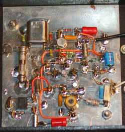
The photo above shows a prototype built with metal transistors (just for looks!) and with a few additions like the variable capacitor in series with the crystal for fine tuning and the variable inductor in the collector of the output transistor. Circuit construction is mostly non-critical but a few points should be observed. Ground-plane is not mandatory but it helps control parasitic feedback elements when less than perfect layout techniques are used. The two capacitors across the base-collector leads of the diff-amp transistors should have short leads. Bypass the 15 volt supply well, perhaps with additional 1 uF capacitors not shown in the schematic. The 100 ohm emitter resistor in the modulator may be bypassed with a 22 ohm resistor in series with a 470 uf capacitor to increase the modulation sensitivity to about 1 volt peak-to-peak which is typical of many sources. Eliminating the 22 ohm resistor will increase sensitivity to under 100 mv but the linearity will suffer somewhat.
An amplifying audio mixer may be added as shown in fig. 2 if more than one audio source is to be used. The gain resistor might be near 2.8k for typical 300 mv sources or considerably higher for lower level sources. If the signal level is different for each source then vary the 600 ohm resistors to compensate. A larger resistor will reduce the gain. Set the main gain resistor for the weakest source then increase the 600 ohm resistors in the other channels for the proper balance. A fancy mixer panel could be constructed with potentiometers in place of the resistors. Remember that some op-amps are not sufficiently fast to amplify high fidelity audio. For simplicity, choose an internally-compensated audio op-amp such as the LM833. Since the LM833 is a dual op-amp the second amp could be used as a separate pre-amp for a microphone or other low-level sources using the same schematic as the mixer. The output of this amp simply feeds one of the mixer source inputs.
Applications:
![]()
A continuous-loop tape could give sales information to passing cars. Place a sign that says, "tune to xxxAM for information," next to the house or car that is for sale.
![]()
Transmit special seasonal music at Christmas or Halloween to enhance your decorations. (Use a similar sign.)
![]()
Transmit a cassette player or other audio source to the car radio for better sound.
![]()
Make a pair of toy AM band two-way radios by adding inexpensive AM radios. Or talk between cars on a trip using the car radio for reception.
![]()
Make a baby monitor that works with any AM receiver.
![]()
Transmit control tones to a number of cheap AM receivers for unusual remote control applications.
![]()
Build a fully functional radio station for the kids - complete with vu meters, slide faders, and an "on the air" light.
Besides making a nice general purpose radio transmitter the Personal Radio Station is suitable for some nice practical jokes:
Hide the transmitter with a cassette tape player in your personal effects as you ride in the back seat of a friend's car. (Leave out the meter circuit to keep the size down.) Ask your friend to tune in that new radio station - since your transmitter is crystal controlled it will be at the right place on the dial. What your victim hears is up to you. The circuit will work reasonably well with a single 9 volt battery instead of 15 volts. How about a less than desirable school lunch menu for the kids. Or, if you are younger, an unexpected school closing for the day. (I didn't really suggest that one, did I?) A news announcement of your marriage proposal will get results. Local news personalities will probably be delighted to help make a tape.
No comments:
Post a Comment